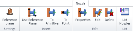
Nozzle tab
In the Component Modeller application, the Nozzle tab contains the following tools.
Using these tools requires that project administrator has created the nozzle construction settings in the project database, as described in Nozzle construction settings. Every nozzle type requires separate construction settings.
You can first import an existing GDL as described in Import to start creating a component model that has nozzles.
Settings

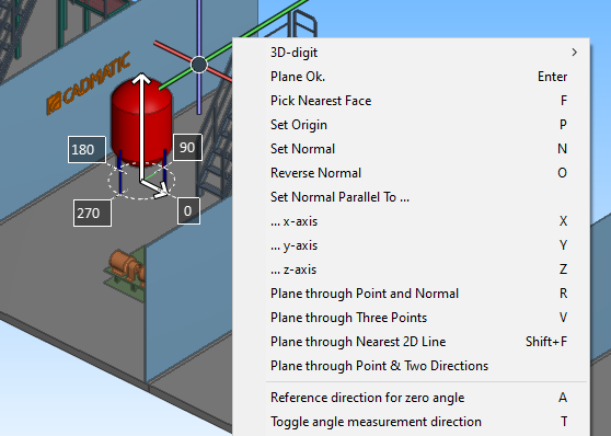
Reference plane
Select Reference plane to define the reference plane to use for nozzle placement when inserting and editing nozzles. Right-click the view to select the required plane with the context-menu commands.
Insert
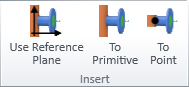
There are three methods for inserting a nozzle.
Use Reference Plane | To Primitive | To Point
Use Reference Plane
You can add a nozzle to the component model by using the reference plane defined in reference plane settings.
Do the following:
-
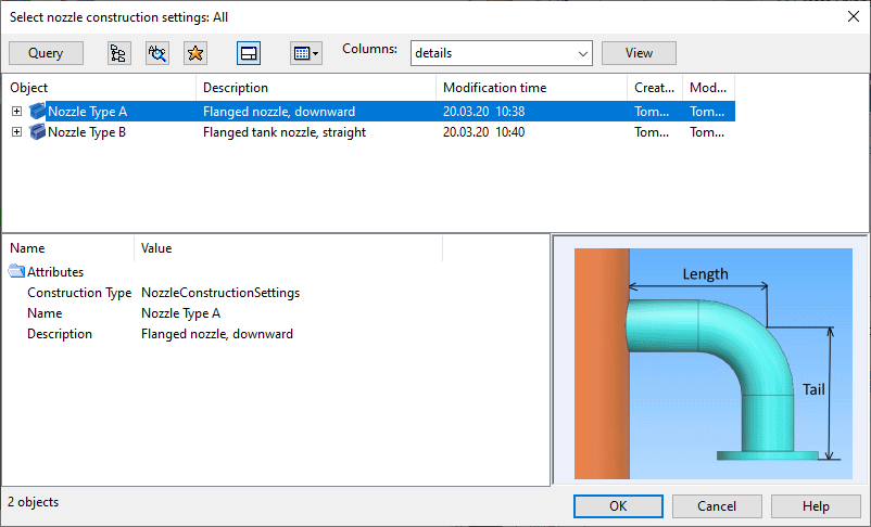
On the Nozzle tab, click Use Reference Plane.
The Select nozzle construction settings dialog opens, listing the available construction settings.
-
Select the nozzle construction settings to use and click OK.
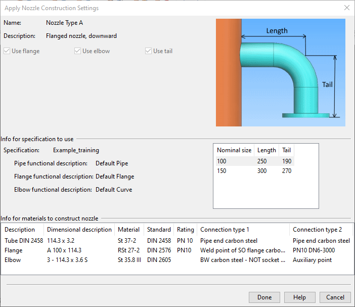
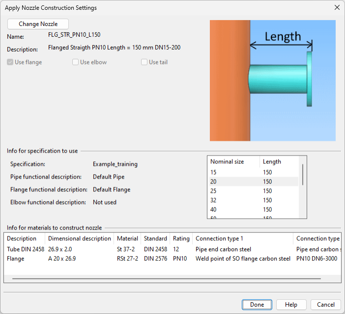
The Apply Nozzle Construction Settings dialog opens, showing the selected construction settings.
-
Select the nominal size to use and click Done.
-
Select the primitive to which to insert the nozzle and press Enter. The nozzle is placed as a transparent object.
-
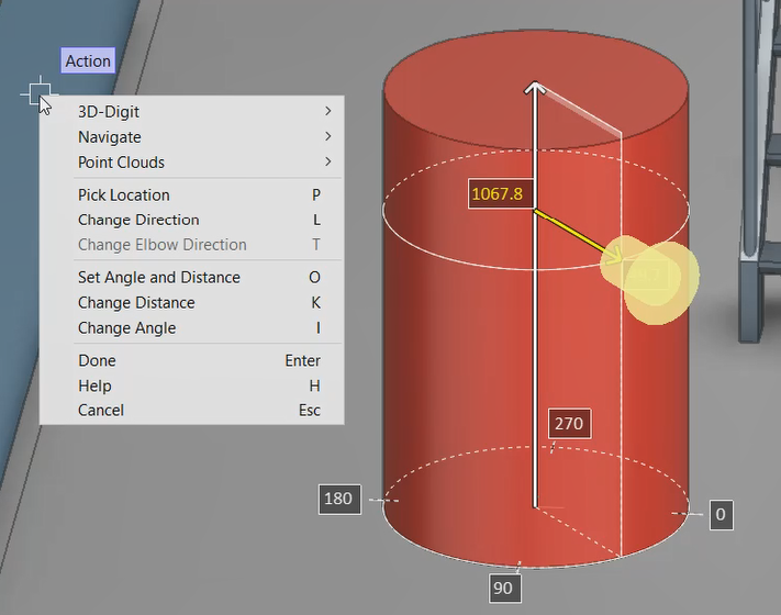
Adjust the location of the nozzle as required. Right-click the view to use these commands:
- Pick location (P)
- Change direction (L)
- Change elbow direction (T)
- Set angle and distance (O)
- Change distance (K)
- Change angle (l)
Tip: Press Ctrl+Tab during Change distance and Change angle operations to input a precise value manually.
-
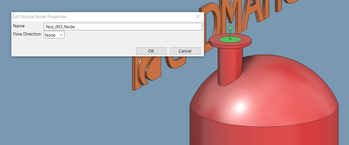
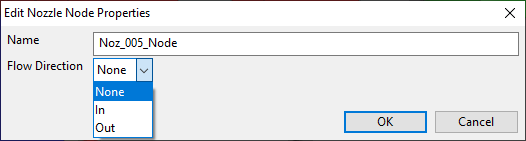
Press Enter to accept the nozzle's location. The Edit Nozzle Node Properties dialog opens.
-
Enter a name for the nozzle node and define node's flow direction if needed, and click OK.
The nozzle is placed in the primitive.
To Primitive
Select To Primitive to place a nozzle to a primitive such as a dish.
Otherwise the process is the same as that described in Use Reference Plane, but instead of using a reference plane you can only use Pick location (P) and Change direction (L) to adjust the nozzle's placement.
To Point
Select To Point to place a nozzle to a specific point, such as a cone's end.
Otherwise the process is the same as that described in Use Reference Plane, but you pick a point instead of a primitive, and you can only use Pick location (P) and Change direction (L) to adjust the nozzle's placement.
Edit
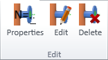
You can manage existing nozzles with the following tools.
Modify | Modify Node | Move | Copy | Delete
Modify
You can choose different nozzle construction settings for existing nozzles and change their size.
Do the following:
-
Select the Nozzle tab > Edit group > Modify.
-
Select an object from the nozzle to modify, then press Enter to confirm the selection.
-
Press Enter to confirm the action. The Apply Nozzle Construction Settings dialog opens.
-
Do the required changes:
-
To choose different nozzle construction settings, click Change Nozzle., select the new settings, and click OK.
-
To change the size of the nozzle, click the new size in the table of available nominal sizes.
-
-
Click Done.
Modify Node
You can modify the name and flow direction of existing nozzles.
Do the following:
-
Select the Nozzle tab > Edit group > Modify Node.
-
Select the node to modify, then press Enter. The Edit Nozzle Node Properties dialog opens.
-
Modify the name and flow direction as required, and click OK.
Move
You can move existing nozzles and change the direction where they are pointing.
Do the following:
-
Select the Nozzle tab > Edit group > Move.
-
Select an object from the nozzle to move, then press Enter to confirm the selection.
-
Press Enter to confirm the action.
-
Use the Pick location (P) and Change direction (L) commands to specify the location and direction of the nozzle.
-
Press Enter to confirm the move.
Copy
You can create copies of existing nozzles.
Do the following:
-
Select the Nozzle tab > Edit group > Copy.
-
Select an object from the nozzle to copy, then press Enter to confirm the selection.
-
Press Enter to confirm the action.
-
Use the Pick location (P) and Change direction (L) commands to specify the location and direction of the new nozzle.
-
Press Enter to confirm the action. The Edit Nozzle Node Properties dialog opens.
-
Enter a name for the new nozzle, specify its flow direction, and click OK.
Delete
You can delete existing nozzles.
Do the following:
-
Select the Nozzle tab > Edit group > Delete.
-
Select an object from the nozzle to delete, then press Enter to confirm the selection.
-
Press Enter to confirm the deletion.
List

List Nozzles
Selecting List Nozzles opens the Nozzle Listing dialog. This dialog lists the nozzles in this GDL and the materials needed for constructing the nozzles.
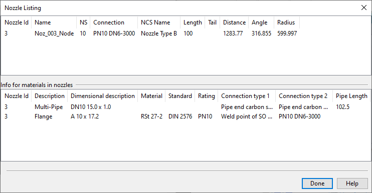
You can use the tools included in the Edit group also through this dialog.
Nozzles
-
Copy – Allows creating a new instance of the selected nozzle.
-
Modify – Opens a dialog for choosing different nozzle construction settings and changing the size of the nozzle.
-
Modify Node – Opens a dialog for modifying the name and flow direction of the selected nozzle.
-
Move Position – Allows changing the location of the selected nozzle and the direction where it is pointing.
-
Delete – Deletes the selected nozzle. You are prompted to confirm the action.
Nozzle material list
-
Export – Exports the material list to a Microsoft Excel file.